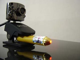
Webcam view:


Howdy folks,
I’ve finally managed to control the stepper motor found in 3 ½ inch floppy drives! It took me almost 3-4 days to accomplish this. The first floppy drive I tried using had a broken stepper motor. So, I went to a computer service center and asked if they had any unused floppy drive they could give to me. They gave me three old floppy drives and didn’t charge anything! I connected these floppy drives to my computer’s motherboard to check if they actually worked. All of them worked perfectly. I opened their outer covering and for the first time had the opportunity to see how a floppy drive works under the hood.
Here are two articles which helped me in controlling the stepper:
According to the instructions on these articles, I tried connecting the floppy drive connector cable to my computer’s parallel port. I didn’t take out the stepper motor from the floppy drive because floppy drives have a built in controller which is capable of controlling the motor. Anyway, the connections I made were:
Floppy Drive--------------------------------Parallel Port
PIN # 18 (Direction)------------------------>PIN # 2 (D0)
PIN # 20 (Step)------------------------------>PIN # 5 (D3)
PIN # 14 -> Ground (Drive Select A)
All odd pins on the floppy drive connector are Ground pins. For example, pins 5, 7, 9 etc.
To make the stepper motor on the floppy drive move, first we have to ground pin 14 on the floppy drive connector. This is done to select the drive electronics. Grounding pin 14 selects Drive A (my floppy drive is jumpered as drive A). Then, we have to send a step pulse to pin 20 of the floppy drive connector to make the stepper move. The direction of movement is determined by the high/low state of pin 18 (the direction pin).
To control the stepper motor through my parallel port, I wrote a program which sent step pulse signal to D0, which is normally high. One low going pulse at step pulse line makes the stepper motor take one step.
All this sounds pretty straight forward, but trust me, I had all the difficulties in the world. The main problem was in my program. The values it sent to the parallel port were incorrect. So after a lot of testing with a multimeter and LED (used as a logic probe), I finally managed to fix it. Now, I am able to control the motor and move it in any direction.
After controlling the motor, I thought, what am I gonna do with this thing? I decided to somehow hook the motor to a camera and move it. With a little bit of construction, I attached the camera to a CD case cover. Then, I hooked the cover to the R/W head on the floppy drive. Whenever the stepper moves the head forward, it pushes the CD case cover open. When it moves backward, it pulls it. Pretty cool, eh? Check out the video and pictures above to get a better idea.
Well, I feel great right now! I can’t tell you how happy I feel. :) This project has taught me a lot about how floppy drives and stepper motors work. Now, my brain is full of all sorts of awesome ideas. I’m planning to write a program which will make the camera turn towards the brightest point in its field of view. In my case, this bright point will be a laser dot. So, if the laser dot is to the camera’s right, the stepper would turn the camera till that dot gets near the center of the camera’s view. Another wonderful implementation could be to make the camera follow a moving person! I already have some experience on motion detection, so this shouldn’t be very difficult.
If you found this post interesting (or even if you didn’t), do send me your comments. I’d love to hear from you. :)
See ya…Keep visiting!


