This blog has moved to https://ashishrd.com/. Check out the new website to see my recent projects!
Saturday, October 14, 2023
Sunday, March 20, 2016
19th century radio technology meets the Beaglebone

In my last post, I described how I made a spark-gap transmitter and receiver. For the transmitter, I used a car's ignition coil to produce high voltage sparks, and for the receiver, I used a coherer to detect the transmissions. A coherer is a simple device - it consists of iron filings between two electrodes. Normally the filings have very high electrical resistance (tens of megaohms), but when the coherer detects electromagnetic waves, its resistance drops to about 10-20 ohms.
Back in the day, spark gap transmitters and coherers were widely used for wireless communication. One of the early pioneers in the field of wireless communication was Arthur "Artie" Moore. He has a very interesting story. As a teenager, he built a steam engine using water-wheel driven lathe, and entered the model in a competition. He received as his prize a book by Sir Oliver Lodge titled "Modern Views of Electricity" which sparked his interest in the world of wireless. He, along with his friend Richard Jenkins, began to experiment with the ideas presented in Lodge’s book. They successfully built their own spark-gap transmitter and coherer receiver and taught themselves Morse code. Artie built a little radio station in his attic, and he would stay there all night listening to signals emanating from ships traveling the coastal waters around Wales.
 |
| Artie Moore's radio shack |
In the early hours of 15 April, 1912, Artie received a faint Morse code signal on his coherer receiver:
"CQD Titanic 41.44N 50.24W."
CQD meant "come quickly distress." In its next message, the ship also used the newer SOS signal -
"CQD CQD SOS de MGY Position 41.44N 50.24W. Require immediate assistance. Come at once. We have struck an iceberg. Sinking."
Artie was copying the signals, hardly believing the words he was writing. The final transmission he received was - "Come as quickly as possible old man; our engine-room is filling up to the boilers."
The RMS Titanic was sinking in the North Atlantic with more than 2,000 passengers and crew, and Artie was receiving the oceanliner’s final distress calls almost 3,000 miles away on his homemade radio. Artie continued to copy the increasingly desperate messages until the Titanic went silent about two hours after the first distress call.
The news of the disaster had not reached UK at that time, and no one believed Artie when he said that the Titanic was sinking. They thought that the Titanic was unsinkable. It was only two days later when it was announced in the national press, people realized he had been right. The receiving of these signals is believed to be the only land-based reception of the Titanic’s last transmissions in the UK, possibly the world.
 |
| Titanic's wireless room replica |
The receiver
Getting back to our story, I built my own coherer in a vinyl tube with iron filings:
 |
| Iron filings coherer |
A problem with the coherer is that once it gets activated, a physical tap is needed to reset it so that it can receive signals again. The system that resets a coherer is called a decoherer. I built a decoherer mechanism using a doorbell. Whenever the coherer gets triggered, it switches on a doorbell, and the bell's hammer hits the coherer and resets it.
 |
| Decoherer mechanism |
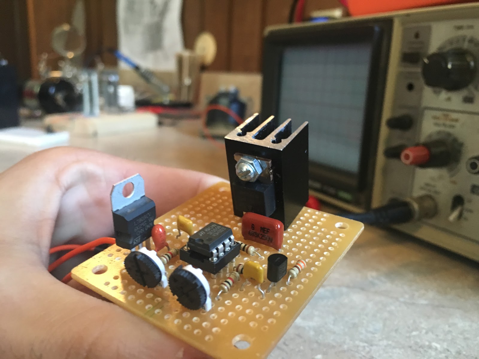
The coherer cannot drive the bell directly, because it draws a lot of current. So, I use a transistor to amplify the signal from the coherer, and the transistor drives a small relay. The relay switches on the doorbell.
 |
| Receiver circuit |
I connected the receiver to a Beaglebone to decode the received signals. I use an optoisolator to connect the output of the receiver to the Beaglebone. The optoisolator is an extra safety precaution to ensure that the Beaglebone is protected from any unwanted transients in the receiver circuit. I also added a flyback diode on the doorbell’s electromagnet to protect the optoisolator. Lastly, you’ll notice that there’s a brown capacitor in the doorbell to reduce sparking on the contacts. This is not necessary, but it should extend the life of the contacts.
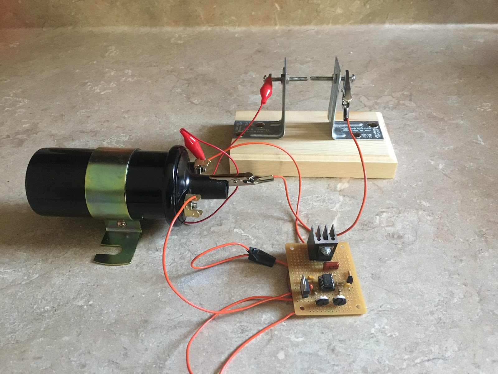
The transmitter
In my previous post, I used a 555 timer-based ignition coil driver in my transmitter. I kept blowing the MOSFETs in that circuit from the inductive kickback produced by the ignition coil. So, I built the driver using a relay instead. The relay has been wired as an oscillator so that it turns the ignition coil on and off very quickly. This electromechanical driver is simpler and a lot more reliable. There's an automotive ballast resistor in the circuit to reduce the current on the primary side. I also salvaged a capacitor (aka condenser) from a car and put it across the relay's poles to reduce arcing on the relay. It's a standard ignition coil capacitor, and it filters out the inductive kickback coming from the coil.
 |
| Transmitter circuit (ignition coil driver) |
 |
| Spark-gap transmitter |
It is important to know that operating spark-transmitters is illegal because they create lots of RF interference. This transmitter can be operated without an antenna to keep the signals from going too far.
Connecting the coherer to a Beaglebone and decoding Morse code!
I connected my coherer to a Beaglebone, and wrote some Python code to decode the messages it receives back to text (receiver circuit above explains the circuit connections). You can find my code here.
Here is a video of the system automatically decoding Morse code signals!
A strange phenomenon
While I was testing my program with the coherer, a loose wire in the receiver's circuit got disconnected, and the decoherer (bell) stopped working. To my surprise, I noticed that my program continued to receive the signals I was sending, and it was even correctly decoding them back to text! How could the system work if the decoherer wasn't even resetting the coherer? I disconnected the Beaglebone from the receiver, and just kept the interface circuit (the optoisolator) connected to it. Now, the receiver wasn't even connected to the Beaglebone. I started sending signals with my transmitter, and to my surprise, the same thing happened again. The Beaglebone was receiving the signals and decoding them! It took me a moment to realize that I had accidentally built a crystal radio (aka cat's-whisker radio). The LED inside the optoisolator was receiving the RF from the spark transmissions, and lighting up. The photo-transistor darlington pair in the optoisolator was amplifying this weak signal, and this was changing the state of the Beaglebone's GPIO pin. How interesting!
This "unintentionally made" crystal radio receiver doesn't have a very good range (only a couple of feet), but I’m sure it could be improved upon to make a more sensitive receiver (and without any mechanical parts).
I hope you enjoyed this project as much as I did. I'd love to hear your thoughts and comments.
EDIT: There is a better explanation for the strange behavior of the 4N33 optoisolator. I received this comment from Perry Harrington on Hackaday:
"If you look at the 4N33, the base of the darlington pair is brought out to a pin. This pin is left necessarily floating, but a darlington pair has typically a ~10,000 gain, so even a small current on this floating base will result in the pair amplifying a current. The bias transistor will have 3.3ma of current flow through it when fully triggered. My experience with 3.3v logic is that it has a ~2.7v input trigger threshold, so you’re looking at about 2.7ma flowing through the darlington to trigger the BBB. If my math is right, it would take about 270na of stray current to trigger the darlington of the optoisolator without a current being present on the LED.
You could probably replicate the results with a TIP120 wired up the same, with the base pin floating. If you are using a breadboard, the grid tie it is connected to would act as an antenna."
Tuesday, November 17, 2015
Rediscovering the magic of wireless communication
In this modern age of high tech gadgets, it is easy to take the technology around us for granted. If we look at the world around us as if we have never seen it before, it would be impossible not to be filled with awe and wonder. In this article, I will tell you the story behind one of the most important technological inventions of modern times - wireless communication. I will also describe some of my own experiments with high voltage spark transmitters and coherers! But before I talk about those, a little background is necessary to appreciate how they work. We’ll have to step into the shoes of the early pioneers in the field of electricity and see the world in a completely different way!
Many years ago, when there were no cell phones or Internet, a great scientist by the name of Michael Faraday speculated the existence of electromagnetic waves when he observed the influence of magnetic fields on polarized light (Faraday Effect). Faraday speculated that light could be a form of electromagnetic disturbance propagating through space. However, this idea was received with considerable skepticism, and it was rejected by everyone until a mathematician by the name of James Clerk Maxwell proved it mathematically in his paper “The Dynamical Theory of the Electromagnetic Field” (1865). Maxwell predicted the existence of electromagnetic waves that could travel indefinitely at the speed of light until absorbed. He proved their existence mathematically without any experimental proof.
About thirteen years later, David Edward Hughes (an Anglo-American concertina player and inventor) observed something very bizarre. When working on his Induction Balance, a loose contact was creating sparks. Hughes noticed that a telephone circuit connected to his carbon microphone on the other side of the room was somehow picking up that noise. He took the telephone circuit outside, and he could still hear the clicks made from the induction coil up to 500 yards away! You could consider this the first mobile phone call in history. Hughes wrote -
“Further researches proved that an interrupted current in any coil gave out at each interruption such intense extra currents that the whole atmosphere of the room (or in several rooms distant) would have a momentary invisible charge, which became evident if a microphonic joint was used as a receiver with a telephone. This led me to experiment upon the best form of a receiver for these invisible electric waves, which evidently permeated great distances, and through all apparent obstacles such as walls &c. I found that all microphonic contacts or joints are extremely sensitive.”
Apparently, when Hughes showed this to members of the Royal Society, the scientists thought it was merely the result of induction. They did not realize that Hughes had accidentally discovered the electromagnetic waves that Maxwell and Faraday had predicted. Hughes never published his findings.
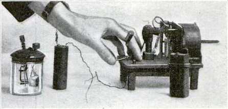 |
| Hughes wireless apparatus, a modified version of his carbon microphone detector (left), and a clockwork driven spark transmitter and battery (right) (source) |
In the 1880s, physicist Heinrich Hertz was trying to confirm the existence of Maxwell’s electromagnetic waves. After observing induced sparking in a Riess spiral, Hertz concluded that this phenomenon could be used to detect the waves. He set up a spark gap transmitter, and a receiver (which consisted of wire loop with a small spark gap). Hertz thought that if the spark gap transmitter created electromagnetic waves, the wire loop antenna would pick it up, and he would see a small spark at the gap in the antenna. Hertz would look at that gap in a dark room with a magnifying glass to see if any sparks appeared.
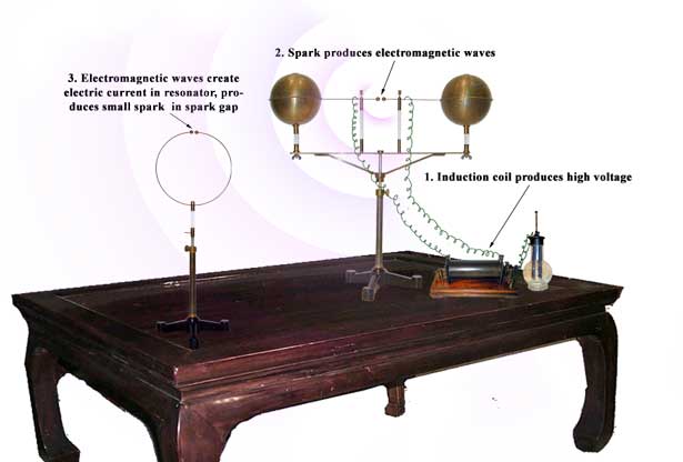 |
| source: http://www.sparkmuseum.com/ |
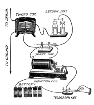
Around the same time, a scientist named Oliver Lodge was investigating some issues with lightning rods. To simulate lightning, he was using two Leyden jars to create high voltage sparks. He had two wires connected to the gap (as shown in the figure below) with multiple spark gaps between them. He observed that when the Leyden jars discharged, sparks appeared at all the spark gaps simultaneously. He also noticed that sparks at certain locations were more intense than others. In a darkened room, he could clearly see a visible glow between the wires at one-half wavelength intervals. When Lodge saw this pattern, he knew that he had discovered the electromagnetic waves predicted by Maxwell.
 |
| Oliver Lodge's experiment (source: "Oliver Lodge: Almost the Father of Radio" by James Rybak) |
Hertz also saw the spark he was hoping to see. Through the experiments of Lodge and Hertz, the existence of Maxwell’s elusive electromagnetic waves was finally confirmed.
Lodge went on to design better devices (detectors) to detect these waves. The detector that Lodge used was called a “coherer”. I think it was based on the idea of Hughe’s carbon microphone detector. A coherer consists of iron filings between two electrodes. Normally, the resistance between the two electrodes is very high. When a spark is created, the resistance between the electrodes drops.
My homemade coherer
After reading the story behind the discovery of electromagnetic waves, I wanted to make my own coherer. The amazing thing about the coherer is how simple it is. Why it works is also mysterious. It seems the electromagnetic waves somehow magnetize the filings, and they get closer to each other. I built my coherer inside a vinyl tube with iron filings between two ¼” bolts.
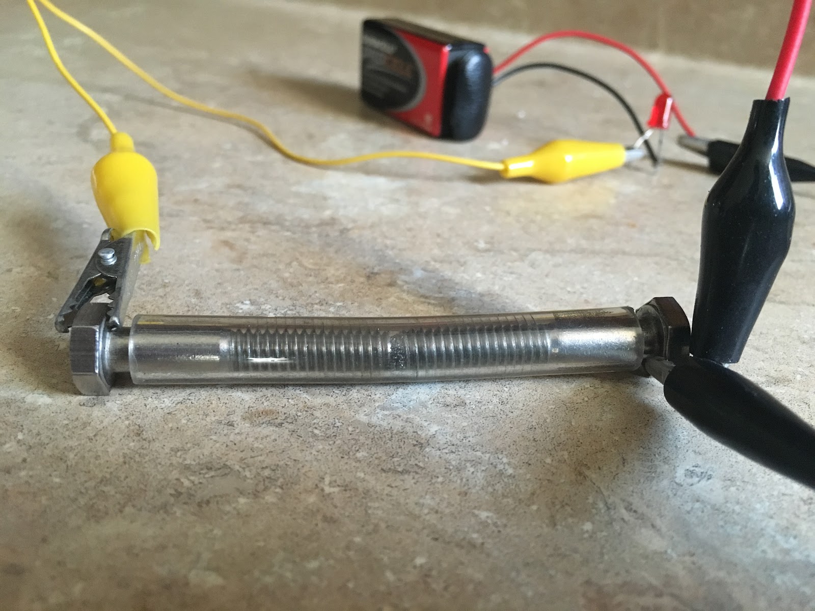
I noticed that a very small amount of filings is required between the bolts for the coherer to work. Also, the performance of the coherer depends a lot on the gap between the bolts. I adjust the gap by first pushing the bolts until my multimeter (in continuity checking mode) beeps. Then, I pull the bolts out just a little until it stops beeping. That seems to be the perfect gap. Normally, the resistance between the two bolts will be very high - in megaohms. When the coherer detects electromagnetic waves, the resistance drops to 10-20 ohms. Normally the coherer will stay in this state of low resistance, and you have to tap it to decohere it. I am thinking about making an automatic tapping mechanism with an electromagnet.
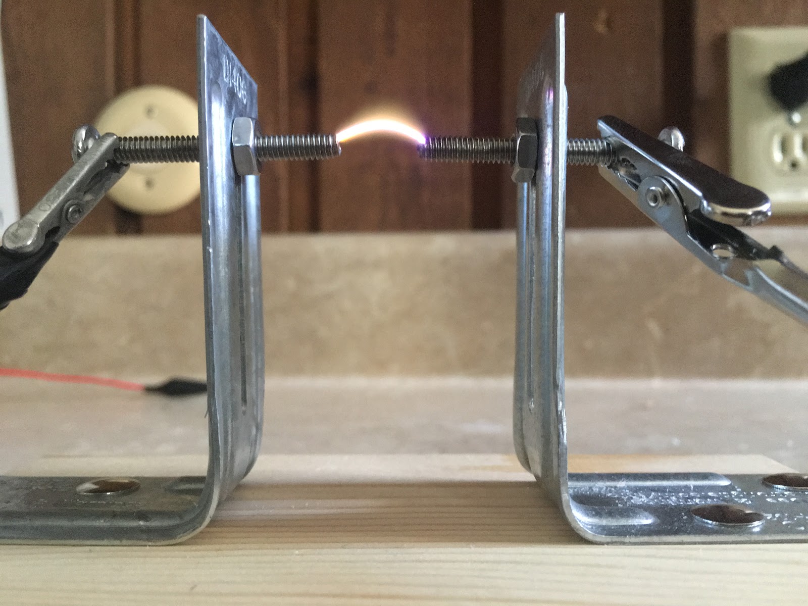
Spark-gap transmitter
To test my coherer, I used a piezoelectric stove lighter. The electric spark created by the lighter was able to trigger the coherer, but it was not very reliable. So, I decided to build a better spark transmitter. I went to a junkyard and salvaged an ignition coil from a car. An ignition coil is a step-up transformer which converts 12V (from the car’s battery) to 20,000V-30,000V. This high voltage is sent to the spark plug to create sparks.
There are different kinds of ignition coils. To identify the coils, you could measure the resistance on the primary and secondary coils. The primary coil should have a very low resistance in the range of 0.4 to 2 ohms, and the secondary should have high resistance in the range of 6K to 15K ohms.
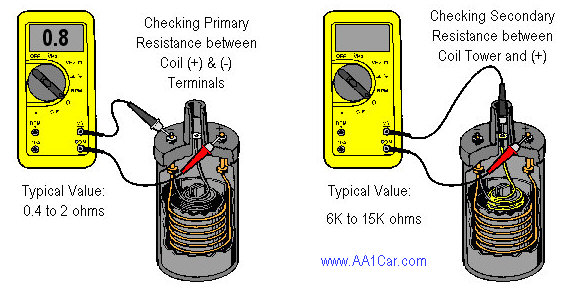 |
| source: http://www.aa1car.com/library/ignition_coils.htm |
To test the coil, I connected a 9V battery to the coil’s primary. That was enough to create a spark on the secondary coil. When I told my dad about it, he shared his wisdom on how a car’s ignition system works, and said that I could improve the sparks if I add a capacitor across the contact point. In a car’s ignition system, there is a capacitor (aka condenser) across the contact breaker. This capacitor absorbs the back-EMF generated by the ignition coil, and reduces arcing on the primary side. This has two benefits. The first is that it improves the life of the contact breaker by reducing burning, and the second benefit is that it results in more intense sparks on the secondary. This is because the magnetic field collapses quicker when the capacitor absorbs the transient back-EMF generated on the primary side, and this increases the induced EMF on the secondary.
So, I looked around in my workspace for a capacitor with a high enough voltage rating, but didn’t find any. Then, I got an idea while watching BBC’s “Shock and Awe: The Story of Electricity” presented by Jim Al-Khalili). In this show, they described how a Dutch scientist by the name of Pieter van Musschenbroek discovered how to store electricity. Before Musschenbroek’s discovery, people could generate electricity with devices like the Hauksbee generator, but did not know how to store it. In those days, people believed that electricity was like an invisible fluid. Using this analogy, Musschenbroek thought that if electricity is like a fluid, it should be possible to store it in a jar, just like we store water! So, he filled a jar with water, and used that to store electricity. He made what’s called a Leiden (or Leyden) jar (named after a Dutch town named Leiden). The Leyden jar was the first capacitor.
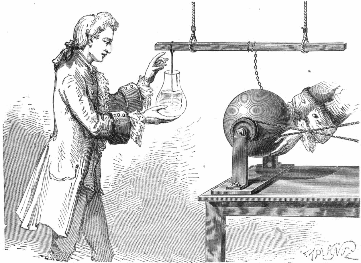 |
| Musschenbroek's Leyden jar (source) |
Later, I designed an ignition coil driver circuit using a 555 timer for continuous sparks. After a lot of trial and error, and blowing several 555s, this circuit seems to be working reliably.
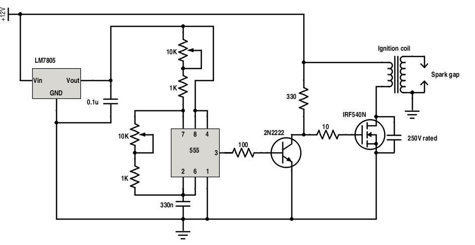
You could adjust the potentiometers to change the 555’s output waveform, and this also changes the quality of the sparks.
I have also tried connecting two ignition coils (in reverse-parallel configuration) to increase the output voltage. Based on the length of the spark gap and the dielectric breakdown voltage of air, I estimated the voltage to be somewhere around 60,000V! Be very careful when doing these experiments. Contrary to what you may want to believe, 60kV shocks don’t exactly feel pleasant (words of experience). I got lucky. Seriously, be very careful when working with high voltages. Carelessness could be fatal. Don’t get close to the spark gap or to any antenna connected to the transmitter.
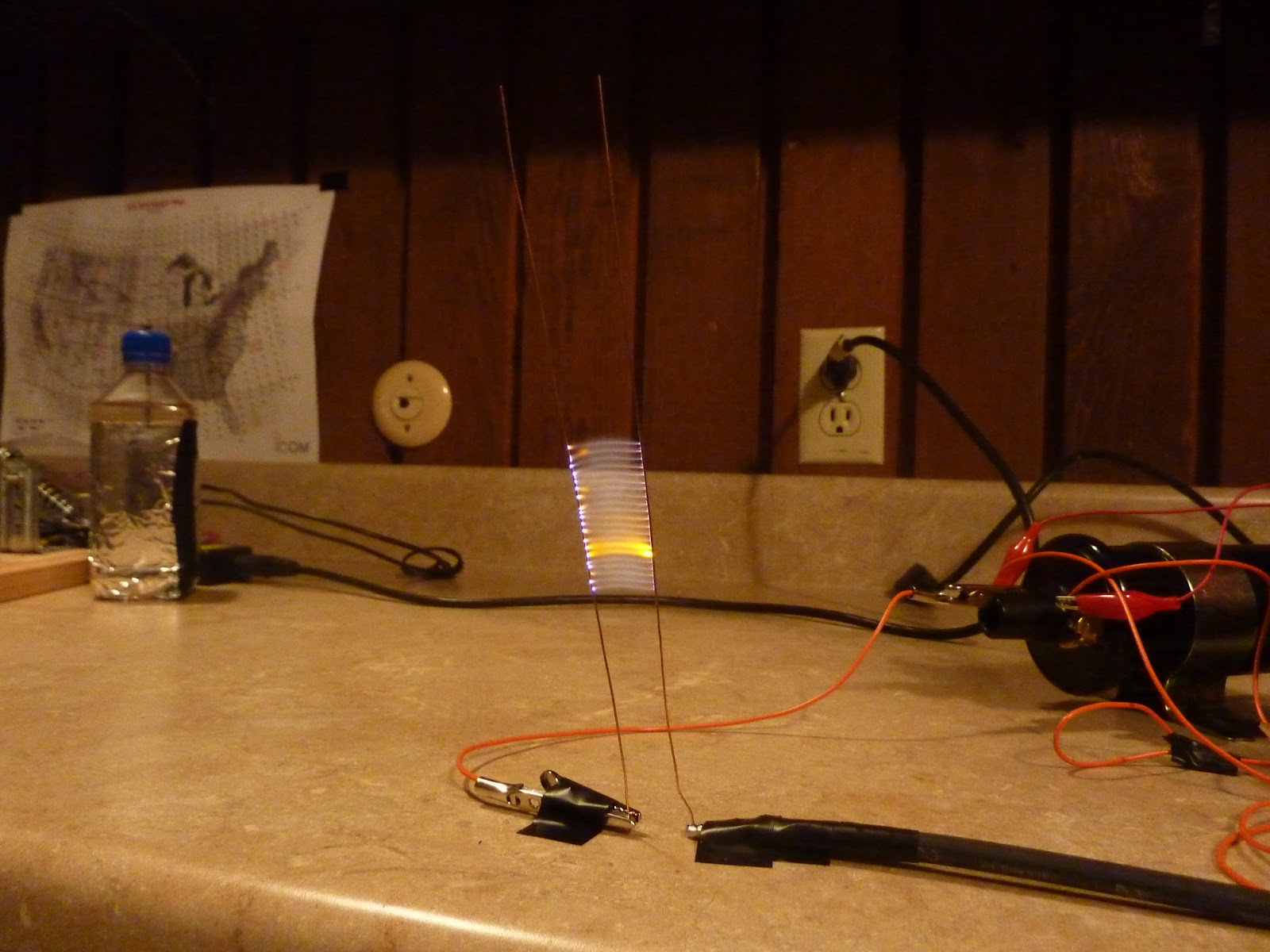
Anyway, here’s a video of my spark transmitter and coherer:
This transmitter can reliably trigger the coherer from a distance. I’m now thinking of ways to extend the range. Back in the day, when spark-transmitters were actually used for communication, people realized that adding a high voltage capacitor on the coil’s secondary could increase the gap current by orders of magnitude without changing the transmitter input power. See “How Spark Transmitter’s Work” by Hal Kennedy.
A tuning coil and capacitor could be added to the ignition coil’s secondary to form a tuned circuit. When the capacitor is fully charged, it will discharge through the tuning coil and spark gap which will cause the capacitor and tuning coil to resonate at their resonant frequency. This will reduce the bandwidth of the electromagnetic waves created from the sparks and increase the range of the transmissions.
 |
| source: “How Spark Transmitters Work” by Hal Kennedy |
By the way, when you have high voltage at your disposal, don’t miss the opportunity to make a Jacbob’s ladder, just like Dr. Frankenstein!
 |
| “It’s alive! It’s alive!” - Dr. Frankenstein |
Tuesday, June 23, 2015
Motion sensing water gun Tweets photos!

I have used Node-RED and Python to link the Bean to a Twitter account. The Node-RED flow runs on a computer, and wirelessly monitors the Bean's serial output. If the Bean detects motion, the computer takes a picture, and uploads it to Twitter. The Node-RED server can also monitor the Twitter account for incoming direct messages. If I send a message with the correct password, I can enable or disable the system. This way I can turn the system off before I enter the office, and turn it on after I leave. It has been driving people crazy here, so I think this project is a success! Check out the tutorial on Instructables (be sure to vote for it if you like it)! :)
Subscribe to:
Posts (Atom)